Tags: madeof:atoms, madeof:bits, craft:electronics, craft:paper
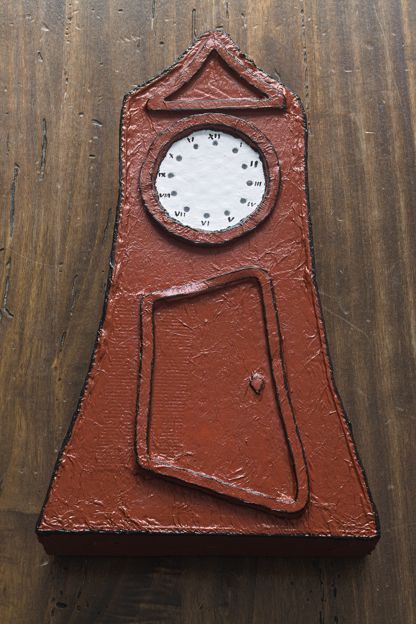
Remember the Conference Talk Timeout Ring? Well, things may have escalated a bit.
The first thing that happened is that I may have accidentally added more RGB LED rings, one for each size to an order of things that we actually needed, because they were cheap and potentially shiny (and I may have ideas that involve the big ones, but they are still just vague ideas).
When they arrived, I played a bit with them to check that they were working, and one was used in a pinch as a light while soldering, and worked nicely.
In the same order there was also a Raspberry Pico2 W and I decided to use it instead of the ESP32-C3-DevKit-Lipo I’ve used a lot lately because it has better support1 in CircuitPython.
So, I have an RGB LED ring with a multiple of 12 LEDs and a microcontroller board with a lot of memory and wifi, what I’m going to do? a grandfather clock, obviously. Except our grandfathers didn’t exactly have LEDs, so it’s going to be a granddaughter clock.
Have I mentioned that things escalated? well, of course I wanted the clock to show the time, but I also wanted it to be able to turn into a flashlight, and to run a countdown for conference talks and any other need, and to tell me if there are things that need to be taken care of around the house, and…
And I have an MQTT server and a number of sensors around the house that provide environmental data, and I decided I might as well use it for other things.
So I designed this to listen to an MQTT topic for commands, another MQTT topic for data, and to switch between modes when instructed to do so by a command.
Other considerations included the fact that this is keeping a number of LEDs on, so I didn’t even try to reduce power usage to run it on battery power for significant amounts (weeks) of time (although running it from a power bank seems to work for shorter durations — I’m thinking a day or two).
And then it was time to fix the part where recognising the first LED on a ring is hard, and I decided to grab my Art Attack supplies and make a case in the shape of a grandfather clock, scaled down to a suitable size for keeping on a desk or bookcase.
I used some IKEA box to make a structure, glued it with hot glue, and then wrapped everything with paper napkins and PVA for added strength, plus a bit of tarlatan for the door hinge.
I opted for a very cartoonish look (and yes, if you are old enough that it resembles something, there was a vague source of inspiration in a cultural artefact of the early 1990) with just a clock face that fits in by friction, a hinged door to access the electronics and a bit of decorative trimming at the top.
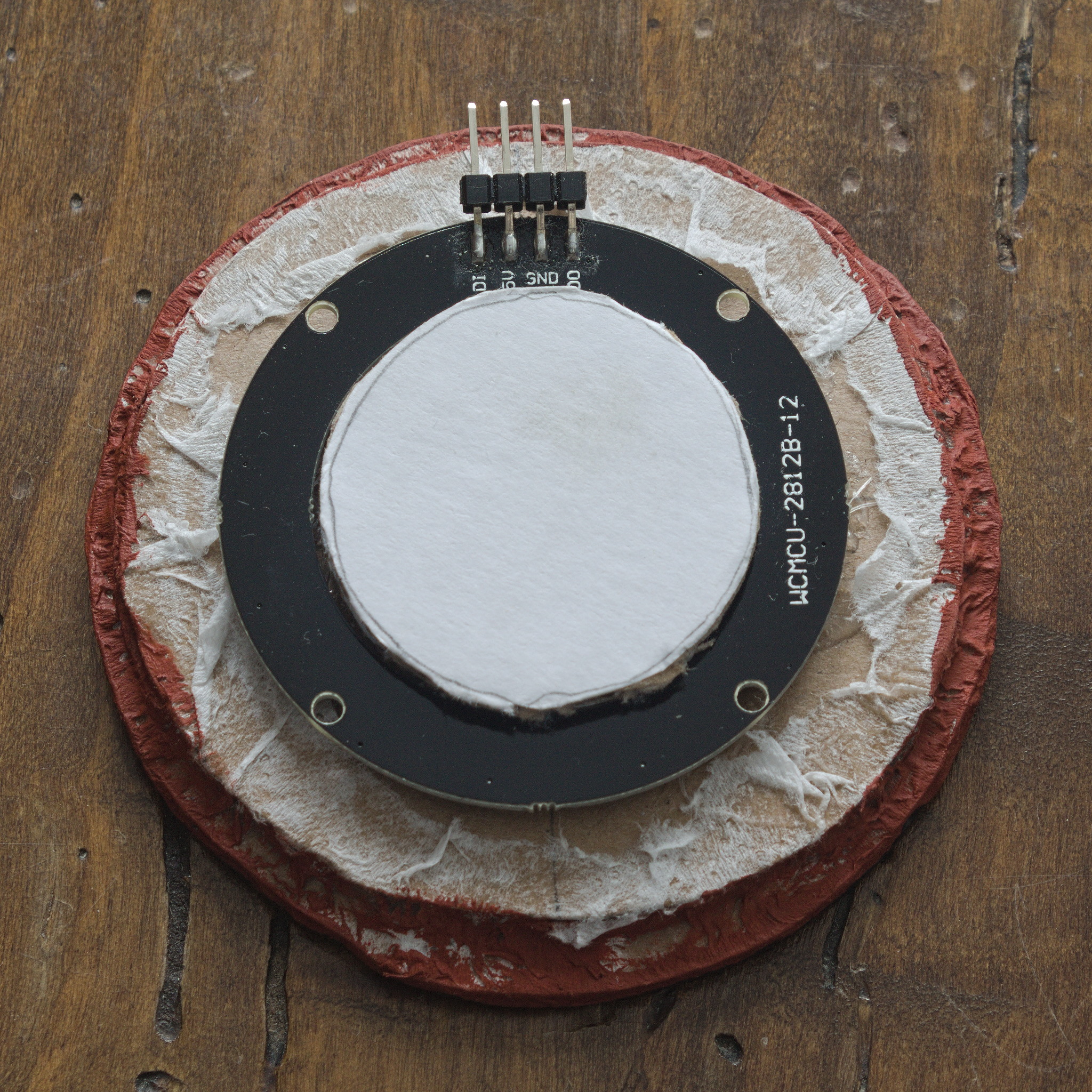
For the face I decided to make holes in the cardboard and fill them with hot glue to make a sort of light pipe, with the LEDs pressed against them on the inside. It’s not perfect, but it mostly works.
And then everything stopped: while I waited for the PVA to dry I started doing something else, and then there were other projects, and other, and the clock lingered in the Pile. There was a brief interruption as I started to paint the first coat of brown, and then I moved back to the other projects.
Until, months later, I decided it was time to finish using the brown and white tubes of paint that I had on my desktop, so I could put them away 2, and in a reasonable time I finished painting the clock, including a second coat of brown, and black contour lines to add a bit of depth in a way consistent with the cartoonish look.
And then it was time to go back to the internals: I got the LED ring and raspberry pico back from their respective drawers, connected them with dupont cables and fit them in the case for a test: it worked.
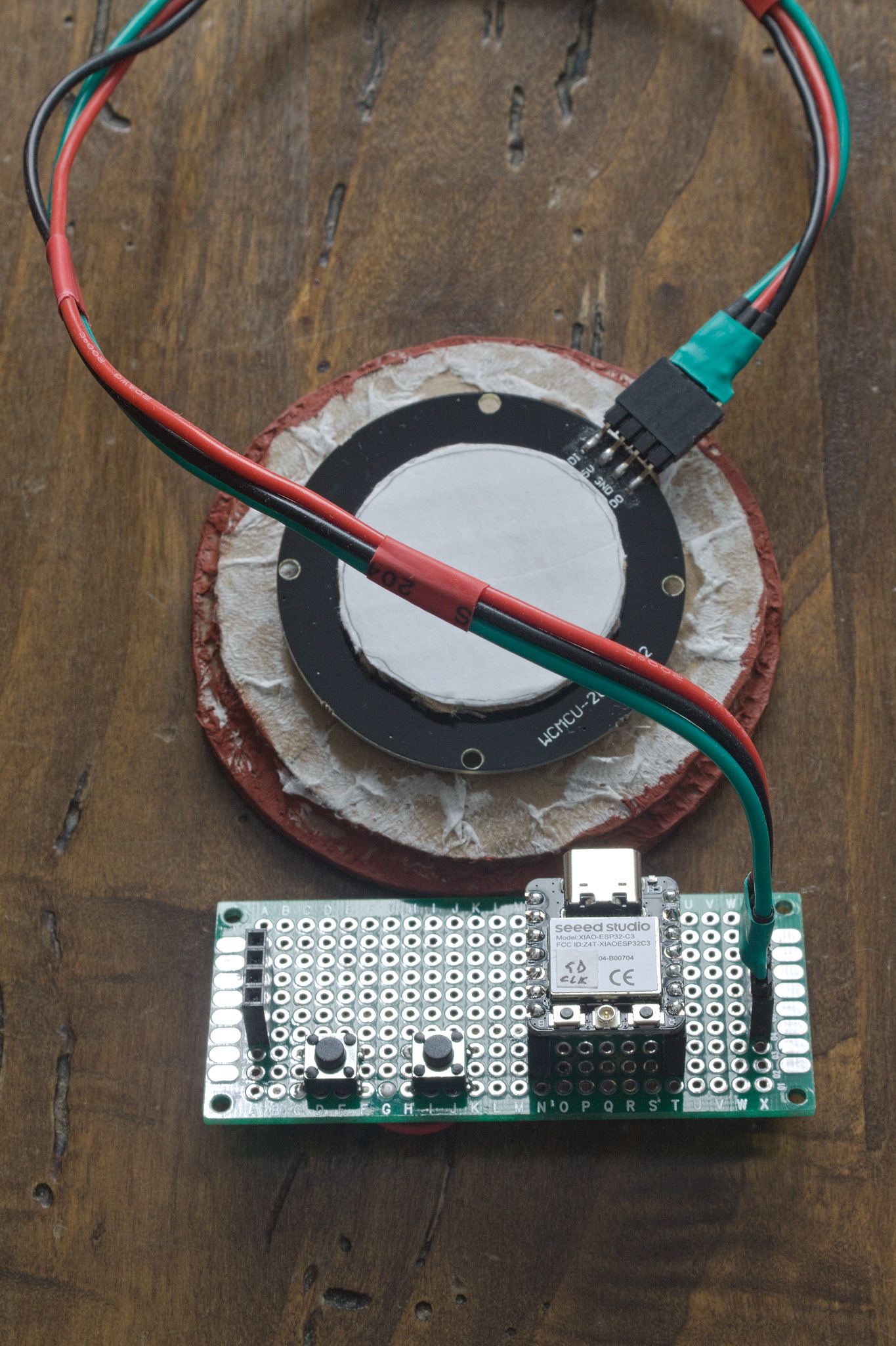
However, the raspberry had quite a lot of pins, and it felt wasteful to use it on something that basically needs one. On the other hand, I had recently bought a few Seed Studio XIAO ESP32C3 for another project3, and those are quite smaller, and also slightly cheaper, and I could spare one out of the 13 I had.
Up to now on the XIAO boards I had been using MicroPython: I had
started to use it on the ESP32-C3-DevKit-Lipo because, contrary to
CircuitPython, the generic ESP32-C3 image worked on it, and on the ESP32
boards there is no CIRCUITPYTHON partition, which in my opinion is
one of the advantages that make CircuitPython more convenient to use
than MicroPython.
However, the code I had already written for the clock used CircuitPython, so I flashed one of the XIAOs with the other interpreter, and after changing just one pin definition the software I had worked.
Going back and forwards between the two interpreters will be interesting, especially since I have already started to write some code for the other project in MicroPython, and they are supposed to interoperate. I may end up rewriting one of them, if I start getting hindered by the subtle differences.
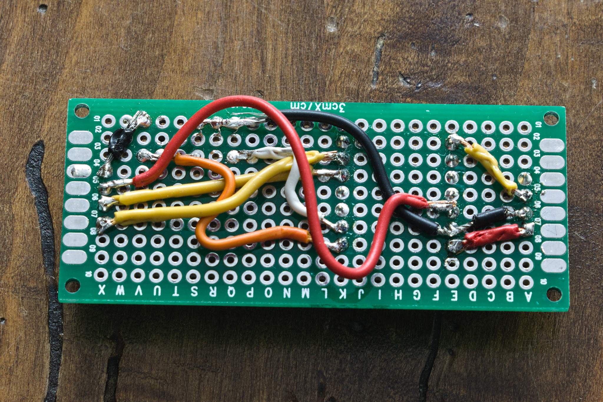
The next step involved dealing with the temporary connections to make them a bit more permanent: I have been using LibrePCB for that other project, so of course what I did was… grabbing a bit of perfboard and YOLO a growing rat nest of cables over it, without bothering with drawing any kind of schematics in advance. And having to desolder stuff and solder it again a couple of times, because I had issues with the difference between left and right, and with the concept of rotations in 3D space.
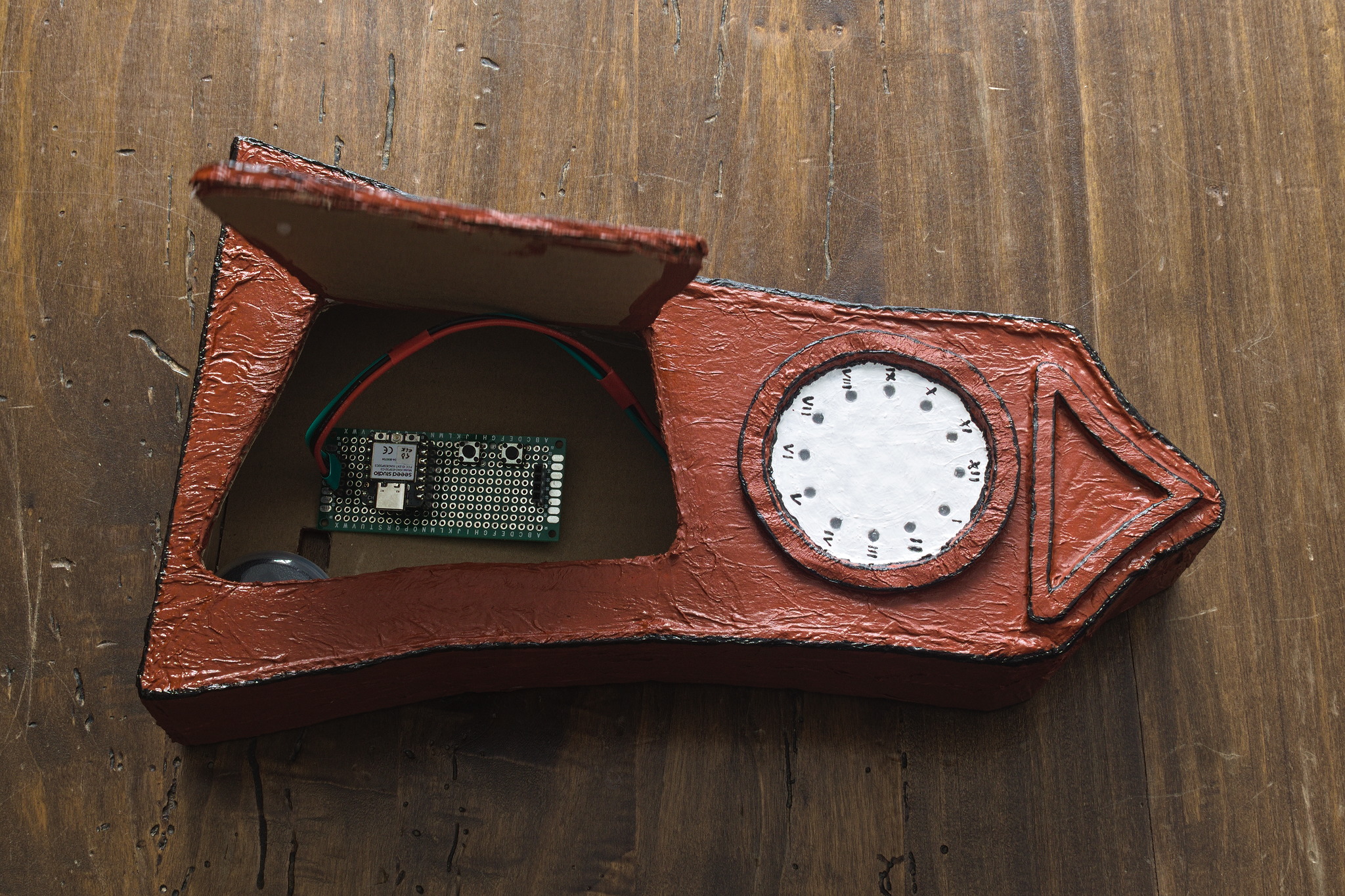
Everything was brought back into the case, in a mostly stable configuration with an usb cable coming out of a hole in the back for power and surprisingly it works.
Or at least, 95% of the issues it still has are software, plus I still need to add a few features, so right now it lives above my desktop, with the cable dangling close to an USB port, so that I can continue working on that in the next few weeks.
The external look is not going to change, so there will be changes on the git repository, and there may or not be a third post here in the future, depending on whether there will be something funny or interesting, or it will just be small incremental improvements.
I think that CircuitPython on the ESP32-C3-DevKit-Lipo only requires fixing two PIN definitions in the files for a very similar board and a recompile, but the latter part looks like a PITA and I haven’t committed to it.↩︎
to make room for other crafting supplies for other projects, of course.↩︎
yes, it will be blogged! unless it fails in a catastrophic way and gets buried under a layer of litter to forget about it. :D↩︎